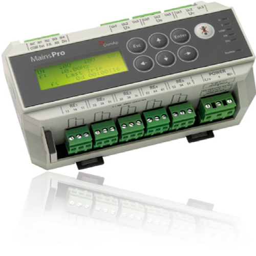
MainsPro Mains Decoupling Protection Relay (G59)


- True RMS measurement
- Universal Power Supply: 8-40V DC, 85-265V AC, 110-370V DC
- Selectable Voltage range: 120/230/400VAC with over-range to 156/290/520V AC (independent)
- Vector Shift and Rate of change of frequency (ROCOF)
- Symmetrical components for better detection of Voltage asymmetry failure
- Two stage settings of voltage and frequency protections to cover short-term as well as long term disturbances with appropriate
- 5 Relay outputs allowing wide range of signalling and trip methods
- Last trip recorded providing evidence of the cause
- 4 Binary switches to remotely change operation of the unit
- Adjustable time delay of Automatic Fault Reset
Product Details
With MainsPro, no special knowledge is needed for installation and no additional units are required, making the ideal solution for both untrained personnel and professionals alike. the unit is designed to fully comply with utilities’ connexion requirements and statutory codes, offering a high level of protection and safety when working in parallel to the mains.
Standards
- MPLY: IEC 602 55
- G59 and G59/2
- UL Approved
- VDE-V-0126-1-1
- IEn NR 005
Efficient Installation
- Flexible supply Voltage range
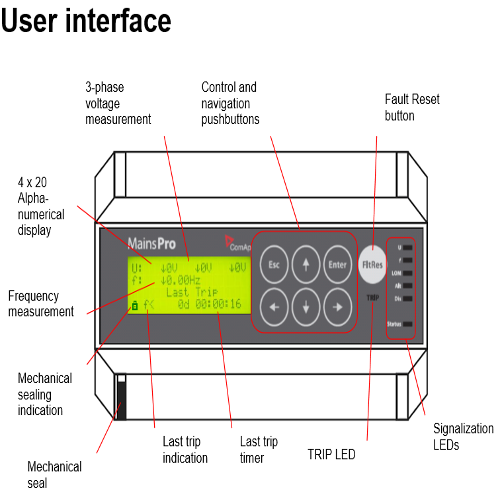
- Friendly interface with easy settings of values
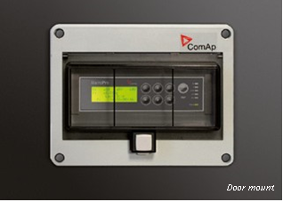
- Suitable for standard DIN-Rail installation or Panel-Mount (Optional)
- Compact design
- Simple Wiring
- Integrated mechanical lock to secure your setting
Protective Functionality
- Undervoltage
- Overvoltage
- Overfrequency
- Underfrequency
- VectorShift
- Rate of change of frequency + ROCOF filter
- Voltage asymmetry
- Positive sequence undervoltage
- Negative sequence overvoltage
- Phase sequence supervison
- Binary switches: Ext. trip, Fault reset, active/de-active, alternative parameters
Product Specification
LED Meanings
| Meaning of signalling LEDs | ||
| LED | Colour | Meaning |
| TRIP | Red | The unit has the appropriate outputs in TRIP position and the unit is sensing a fault situation |
| Red flashing | The unit has the appropriate outputs in TRIP position, but the unit is sensing fault-free situation. Fault reset is possible. | |
| Nothing | The unit has no output in TRIP position | |
| U | Red flashing | Voltage of any phase is above threshold for 1st or 2nd stage overvoltage |
| Red | Voltage of any phase is under threshold for 1st or 2nd stage undervoltage | |
| Orange flashing | Voltage unbalance (amplitude) is indicated. | |
| If activated together with LED f and LOM, indicates incorrect phase rotation | ||
| Orange | Negative sequence overvoltage or Positive sequence undervoltage is indicated. | |
| If activated together with LED f and LOM, indicates incorrect polarity of one phase | ||
| Green | All voltages are in fault-free state | |
| Green flashing | 10 minutes floating average overvoltage is detected | |
| Nothing | Over/under voltage protections are not enabled by setpoint and no other voltage failure is sensed | |
| f | Red flashing | Frequency as sensed on terminals Ua is above threshold for 1st or 2nd stage overfrequency |
| Red | Frequency as sensed on terminals Ua is under threshold for 1st or 2nd stage underfrequency | |
| Orange flashing | Together with LED U and LOM, indicates incorrect phase rotation | |
| Orange | Together with LED U and LOM, indicates incorrect polarity of one phase | |
| Green | Frequency, rotation and phases polarity are in fault-free state | |
| Nothing | Over/under frequency is protections are not enabled by setpoint and no other indicated failure is sensed | |
| LOM | Red | Vector shift or ROCOF protection was indicated and Fault reset was not yet done |
| Orange flashing | Together with LED U and f, indicates incorrect phase rotation | |
| Orange | Together with LED U and f, indicates incorrect polarity of one phase | |
| Nothing | None of Vector shift or ROCOF failure is detected or neither Vector shift nor ROCOF protections are not enabled by setpoint and no other indicated failure is sensed | |
| Status | Red flashing | Indication of severe internal failure. Contact ComAp technical support! |

| Meaning of signalling LEDs | ||
| LED | Colour | Meaning |
|
| Orange flashing | Indication of internal failure. Contact ComAp technical support! |
| Orange | Indication of internal failure. Contact ComAp technical support! | |
| Green | The unit is in operation with no internal problems. | |
| Nothing | The unit is not in operation | |
| Alt | Orange | The function Alternative setting is activated by means of binary switch Alt setting. |
| Nothing | The function Alternative setting is not activated | |
| Dis | Orange | The unit is disabled by means of binary switch Disable |
| Nothing | The unit is not disabled by means of binary switch Disable |